Introduction
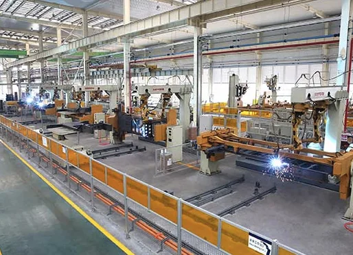
Wind turbine componentsmonopile foundations, tower sections, pitch control tubing, and yaw drive wear surfacesrequire welds with consistent fatigue resistance, corrosion performance, and wear life to meet 20+ year service targets. Automated welding reduces process variability vs.
manual methods, but precise heat input control is critical to avoid microstructural degradation, residual stress, and dilution-related failures. This article covers core process fundamentals, heat input optimization, defect mitigation, and compliance for wind power welding.
Core Automated Welding Processes for Wind Power

Thick-Section Structural Welding
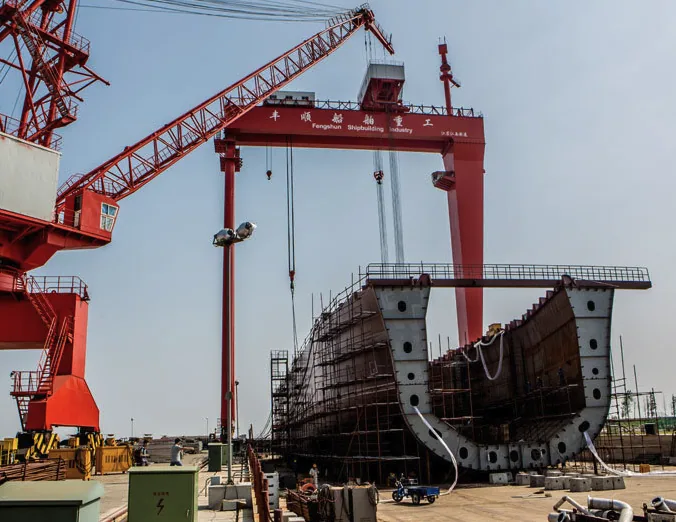
Tandem-wire submerged arc welding (SAW) is the primary automated process for monopile and tower fabrication. These components range up to 4267.2mm (168) OD with wall thicknesses up to 100mm, requiring high deposition rates while maintaining strict heat-affected zone (HAZ) toughness control. Heat input directly dictates HAZ grain size, the primary driver of fatigue resistance for cyclically loaded wind components.
Cladding and Tube-End Preparation
Corrosion-resistant cladding for offshore monopile splash zones and hydraulic tube ends uses automated hot-wire TIG for precise layer control. Automated orbital beveling machines handle 3mm to 4267.2mm OD tubes across all structural and alloy materials, eliminating manual grind variability. Lightweight clamping heads for 3mm to 219mm OD tubes perform squaring and facing in one setup, ideal for on-site maintenance.
| Layer Number | Thickness Range (mm) | Travel Speed (mm/min) | Deposition Rate (kg/h) | Dilution Rate |
|---|---|---|---|---|
| 1 (bond layer) | 1.5 3.5 | 500 1000 | 2.5 6 | ~12% |
| 2+ (functional layer) | 1.5 3.5 | 500 1000 | 2.5 6 | 1.5 2% |
Table 1: Automated cladding parameters for wind component corrosion overlays.
Hardfacing for Wear Protection
Wind turbine yaw drive rollers, pitch cylinder rods, and gearbox-adjacent wear surfaces face abrasive particulate exposure (desert dust, offshore salt), which drives 67% of wear-related failures in heavy industrial applications. For components operating above 500C under extreme load, abrasive wear is significantly amplified, requiring high-alloy hardfacing that retains hardness at elevated temperatures.
This approach is validated in milling applications, where vertical mill rollers operate against 5080mm (slag/clinker) to >300mm (raw mill) material beds; the same wear resistance principles apply to wind yaw rollers, which maintain consistent contact pressure against the bearing track.
Heat Input Control: Principles and Implementation
Heat input is energy delivered per unit weld length, calculated as kJ/mm = (Voltage Current 60) / (Travel Speed 1000). Optimal ranges balance deposition rate, microstructural integrity, and dimensional distortion. For wind applications, tight heat input tolerances ensure compliance with fatigue and corrosion performance requirements.
| Application | Process | Heat Input Range (kJ/mm) | Key Performance Target |
|---|---|---|---|
| Monopile circumferential welds | Tandem SAW | 1.8 3.2 | HAZ toughness 27 J at -40C |
| Splash zone corrosion cladding | Hot-wire TIG | 0.3 0.8 | Dilution <12% (layer 1), <2% (layer 2+) |
| Pitch tube end orbital welds | Pulsed GMAW | 0.2 0.5 | 100% radiographic inspection pass |
| Yaw roller hardfacing | Flux-cored arc welding | 0.6 1.1 | Surface hardness 58 HRC, no cracking |
Table 2: Heat input ranges and performance targets for wind power welding applications.
Common Defects: Root Causes and Countermeasures
- HAZ grain coarsening (reduced fatigue toughness): Root cause: Heat input exceeding 3.5 kJ/mm for S355 structural steel, or interpass temperatures above 250C. Countermeasure: Limit heat input to 1.83.2 kJ/mm for thick-section structural welds, and monitor interpass temperature to maintain 150250C for low-carbon steel.
- Excessive cladding dilution (>15% first layer): Root cause: Low travel speed, incorrect wire feed angle, or excess current. Countermeasure: Calibrate travel speed to 5001000 mm/min, use a 1520 push angle, and apply pulsed current to reduce heat input while preserving deposition rate.
- Hardfacing surface cracking: Root cause: Insufficient preheat, low heat input, or high alloy carbon equivalent. Countermeasure: Preheat base material to 150200C for high-alloy hardfacing, maintain interpass temperature above 100C, and adjust heat input to 0.61.1 kJ/mm to slow cooling rates.
- Tube end weld porosity: Root cause: Poor bevel surface finish, insufficient shielding gas purge, or contaminated base material. Countermeasure: Use automated orbital beveling to achieve Ra 3.2 m surface finish, and purge the tube ID with argon for 35 minutes before welding.
Applicable Standards
- EN 1090-2: Mandatory for CE-marked wind towers and monopiles, governing structural steel execution.
- DNV-OS-J101: Offshore wind turbine structure design standard, including welding and material requirements.
- AWS D1.1/D1.1M: Structural welding code widely used for onshore wind tower fabrication and repair.
- ISO 15609: Governs welding procedure specification (WPS) development and qualification for all wind power welds.
- API 5L: Pipeline standard applicable to nacelle hydraulic and pitch control tubing welds.
Pre-Weld Inspection Checklist
- Verify base material certification (grade, thickness, chemical composition) matches the approved WPS.
- Confirm bevel geometry (angle, root face, root gap) and squareness meet WPS requirements; for tubes, validate squareness 0.1mm per 100mm OD.
- Inspect joint cleanliness: no oil, rust, mill scale, or moisture within 25mm of the weld fusion zone.
- Calibrate welding parameters (voltage, current, wire feed speed, travel speed, gas flow rate) within 24 hours of production use.
- Confirm preheat temperature (if required) is uniform across the joint, measured 75mm from the weld centerline on both base material sides.
- Validate filler material type, diameter, and storage conditions (no moisture contamination for flux or flux-cored wires).
Frequently Asked Questions
- Q: What is the cost benefit of automated vs. manual cladding for wind components?
A: Automated cladding delivers consistent layer thickness and controlled dilution, reducing rework and cutting operating costs by 2050% per kilogram of weld metal deposited, while meeting strict corrosion performance requirements. - Q: How does heat input affect wind tower weld fatigue life?
A: Excessive heat input causes HAZ grain coarsening, reducing low-temperature Charpy impact toughness and increasing cyclic fatigue failure risk. For offshore wind towers, limiting heat input to 1.83.2 kJ/mm ensures -40C HAZ toughness compliance. - Q: What tube size range do orbital systems handle for wind applications?
A: Automated orbital welding and beveling systems process 3.2mm (1/8) to 4267.2mm (168) OD tubes, with wall thicknesses from 1mm to 100mm. Lightweight clamping heads for 3mm to 219mm OD tubes enable portable on-site maintenance work.
Key Takeaways
- Automated wind power welding processes (tandem SAW, hot-wire TIG cladding, orbital GMAW) require precise heat input control to meet fatigue, corrosion, and wear performance targets.
- Automated cladding delivers 1.53.5mm thick layers with 1.52% dilution for functional layers, cutting operating costs by 2050% per kg of weld metal compared to manual methods.
- Pre-weld inspection and adherence to industry standards (EN 1090-2, DNV-OS-J101, AWS D1.1) are critical to ensuring weld quality for 20+ year wind turbine service life.
- Hardfacing for yaw rollers and pitch system components leverages milling-validated wear principles, where 67% of failures stem from abrasion in particulate-heavy operating environments.
BIQEE @ DESAN ELECTRIC supplies welding automation systems for the Wind Power sector. For technical selection support, contact https://biqee.cn.
Conclusion
Choosing the right welding automation solution is key to improving productivity and quality in your fabrication operations.
Technical Specifications (BIQEE Cutting & Bevelling):Cutting thickness: 5mm 200mm (plasma up to 80mm)
Bevel angle: 0 60 (adjustable)
Cutting speed: 100 3,000 mm/min
Tolerance: 1mm per 10m of cut length