Introduction
Shipbuilding relies on large, precision-matched structural assemblies where even minor welding distortion can compromise hull hydrodynamics, structural integrity, and downstream assembly sequencing. Automated welding systems reduce process variability, but their performance depends entirely on consistent fit-up and proactive distortion control.
This article breaks down the technical fundamentals of automated welding and prep processes for shipbuilding, links fit-up tolerance variability to distortion mechanisms, and provides actionable countermeasures, inspection frameworks, and compliance guidance.
Process Fundamentals for Automated Shipbuilding Welding
Two automated process categories dominate modern shipbuilding: high-deposition structural welding for hull plates and stiffeners, and precision cladding/pipe welding for corrosion-resistant surfaces and piping systems. For corrosion cladding used in ballast tanks, process piping, and cargo hold liners automated hot-wire TIG systems deliver tightly controlled layer geometry.
Optimized cladding layer thickness ranges from 1.5 to 3.5 mm, adjustable to match corrosion or wear design life requirements.
These systems operate at 500 to 1000 mm/min travel speeds, with 2.5 to 6 kg/h deposition rates, balancing productivity and heat input control. Dilution is regulated to ~12% on the first layer for bond integrity, dropping to 1.5 to 2% from the second layer onward to preserve clad alloy corrosion resistance. This control cuts operating costs by 20 to 50% per kilogram of weld metal relative to manual cladding, while reducing residual stress and distortion.
For pipe joints, automated orbital beveling and squaring eliminate manual grinding variability, delivering consistent joint geometry for uniform fit-up. Lightweight clamping units handle 3 mm to 219 mm OD (0.08″ to 8″) tube squaring/facing, while full beveling systems support 3 mm to 4267.2 mm OD (0.118″ to 168″), covering small tubing to large ballast piping.
Compatible with virtually all alloys, these systems handle wall thicknesses 1 mm to 100 mm (0.04″ to 3.937″), with larger sizes on request.
| Parameter | Value Range | Application Note |
|---|---|---|
| Cladding layer thickness | 1.5 to 3.5 mm | Adjusted to match corrosion/wear design life requirements |
| Travel speed | 500 to 1000 mm/min | Higher speeds used for thin-layer cosmetic cladding |
| Deposition rate | 2.5 to 6 kg/h | Matched to base material thickness to limit heat input |
| First-layer dilution rate | ~12% | Controlled via heat input and wire feed speed for bond integrity |
| Subsequent-layer dilution rate | 1.5 to 2% | Maintains consistent clad alloy corrosion resistance |
| Operating cost reduction (per kg weld metal) | 20 to 50% | Relative to manual cladding operations |
Distortion Mechanisms and Fit-Up Tolerance Impacts
Welding distortion in shipbuilding stems from non-uniform thermal expansion and contraction of base and filler material. Common modes include angular distortion, transverse/longitudinal shrinkage, and buckling in thin superstructure plate. Fit-up gap variability is the largest pre-weld distortion driver: excess gap increases weld volume, raising heat input and amplifying all modes.
Distortion Defect Root Causes and Countermeasures
- Root cause: Excessive fit-up gap increasing weld volume and heat input. Countermeasure: Deploy automated orbital beveling and squaring to produce consistent bevel angles and face flatness, minimizing fit-up gap variability.
- Root cause: Unbalanced pass heat input causing asymmetric shrinkage. Countermeasure: Program alternating weld pass sequences for thick joints, and limit cladding layer thickness to 1.5 to 3.5 mm to reduce per-pass heat load.
- Root cause: High cladding dilution causing differential thermal expansion. Countermeasure: Use controlled cladding systems with ~12% first-layer dilution and 1.5 to 2% subsequent-layer dilution to reduce residual stress.
- Root cause: Poor fit-up causing defects that require rework heat. Countermeasure: Implement pre-weld fit-up inspections and use automated seam tracking to adjust for minor deviations.
| Prep Operation | Compatible OD Range | Compatible Wall Thickness Range | Material Compatibility |
|---|---|---|---|
| Orbital beveling | 3 mm to 4267.2 mm (0.118″ to 168″) | 1 mm to 100 mm (0.04″ to 3.937″) | Virtually all structural and corrosion-resistant alloys |
| Tube squaring/facing (lightweight clamping) | 3 mm to 219 mm (0.08″ to 8″) | 1 mm to 100 mm (0.04″ to 3.937″) | Virtually all structural and corrosion-resistant alloys |
| Cladded pipe end preparation | 3.2 mm to 4267.2 mm (1/8″ to 168″) | 1 mm to 100 mm (0.04″ to 3.937″) | Carbon steel, stainless steel, duplex, nickel alloys |
Applicable Industry Standards
Key applicable standards include:
- ISO 15614-1: Governs welding procedure qualification for arc welding of steels and nickel alloys.
- ISO 14322: Defines acceptance levels for welding imperfections, including distortion limits for steel assemblies.
- IACS Unified Requirement W11: Sets fit-up tolerance and distortion acceptance criteria for commercial ship hulls.
- ASME B31.1: Specifies requirements for shipboard power piping, including orbital welding and cladding.
- NORSOK M-601: Outlines welding and inspection requirements for shipboard process piping and corrosion cladding.
Pre-Weld Fit-Up Inspection Checklist
Pre-weld fit-up inspection checklist:
- Verify base material grade, thickness, and cladding spec (1.5 to 3.5 mm nominal, if applicable) match drawings.
- Confirm joint bevel angle, root face depth, and face flatness with calibrated gauges; validate pipe squareness from automated facing.
- Measure fit-up gap and mismatch across the full joint, ensuring alignment with WPS and IACS W11 limits.
- Confirm automated welding parameters (travel speed, deposition rate) match the WPS; for cladding, verify speed is within 500 to 1000 mm/min.
- Check preheat temperature uniformity (if specified) to eliminate cold spots that increase residual stress.
- For cladding, verify dilution settings deliver ~12% first-layer and 1.5 to 2% subsequent-layer dilution.
- Inspect fixturing to ensure rigid, balanced restraint that limits distortion without excessive residual stress.
Frequently Asked Questions
Q: How does automated cladding reduce distortion compared to manual cladding?
A: Automated cladding maintains consistent 500 to 1000 mm/min speeds and 2.5 to 6 kg/h deposition rates, eliminating manual heat variability. Tight dilution control (12% first layer, 1.5 to 2% subsequent layers) minimizes differential expansion, cutting residual stress, distortion, and operating costs by 20 to 50% per kg of weld metal.
Q: What pipe sizes are compatible with automated orbital beveling for shipboard use?
A: Automated orbital beveling supports virtually all materials with diameters 3 mm to 4267.2 mm OD (0.118″ to 168″), covering small tubing to large ballast piping. Wall thicknesses range 1 mm to 100 mm (0.04″ to 3.937″), with larger sizes on request. Lightweight units handle 3 mm to 219 mm OD tubes for small-bore joints.
Q: Why is fit-up tolerance control critical for automated shipbuilding welding?
A: Fit-up gap directly dictates weld volume and heat input, the primary distortion drivers. Excess gaps increase filler use and heat load, amplifying shrinkage and angular distortion. Consistent fit-up from automated prep keeps systems within heat limits, cutting distortion and rework.
Key Takeaways
- Automated cladding delivers 2.5 to 6 kg/h deposition at 500 to 1000 mm/min, with controlled dilution (12% first layer, 1.5 to 2% subsequent layers) and 20 to 50% lower operating costs per kg weld metal than manual methods.
- Automated orbital beveling and squaring supports pipe diameters 3 mm to 4267.2 mm OD, producing consistent joint geometry that minimizes fit-up variability and distortion.
- Proactive fit-up control, validated via pre-weld checklists, is the most impactful pre-weld step for reducing distortion and ensuring compliance with IACS, ISO, and ASME standards.
- Distortion mitigation requires a system-level approach: optimized joint prep, controlled heat input, balanced sequences, and engineered fixturing, enabled by automated technology.
BIQEE @ DESAN ELECTRIC supplies welding automation systems for the Shipbuilding sector. For technical selection support, contact https://biqee.cn.
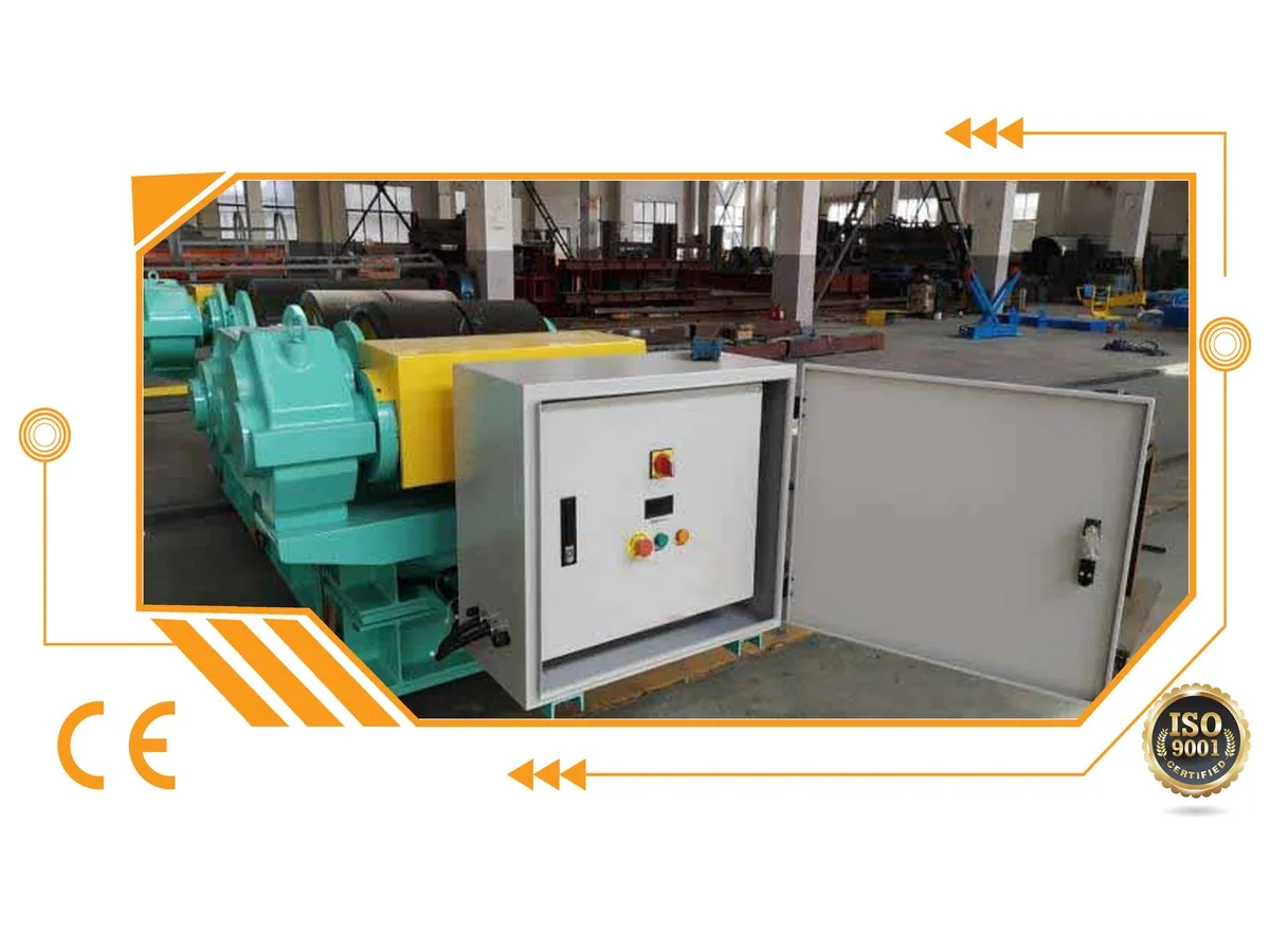
Self-Aligning Welding Rotator (SAR Series)
Technical Specifications:
| Model | Max Load (tons) | Vessel Dia (mm) | Wheel DiaWidth (mm) | Motor Power (kW) | Wheel Speed | Overall Dim (mm) |
|---|---|---|---|---|---|---|
| SAR5 | 5 | 250-2300 | 250140 | 0.75 | 0.1-1 m/min | 1620690700 |
| SAR10 | 10 | 320-2800 | 300170 | 1.5 | 0.1-1 m/min | 1880780820 |
| SAR20 | 20 | 500-3500 | 350180 | 2.2 | 0.1-1 m/min | 2250930950 |
| SAR40 | 40 | 600-4200 | 400200 | 3.0 | 0.1-1 m/min | 250010151050 |
| SAR60 | 60 | 750-4800 | 450220 | 4.0 | 0.1-1 m/min | 300012001100 |
| SAR80 | 80 | 850-5000 | 500240 | 4.0 | 0.1-1 m/min | 320012001250 |
| SAR100 | 100 | 1000-5500 | 50080 (PU) | 5.5 | 0.1-1 m/min | 350014101350 |
| SAR150 | 150 | 1000-6000 | 500220 (Metal) | 6.0 | 0.1-1 m/min | 42009001450 |
| SAR200 | 200 | 1800-8000 | 550260 | 7.5 | 0.1-1 m/min | 48009001500 |
| SAR250 | 250 | 1800-8000 | 660260 | 11 | 0.1-1 m/min | 501011131600 |
| SAR500 | 500 | 1800-8000 | 800300 | 15 | 0.1-1 m/min | 560013702100 |
Note: Variable rotation speed (VFD). Wheels padded with heavy-duty rubber (SAR100 & smaller). Remote control with digital speed display.
For detailed specifications and pricing, contact us at [email protected] or visit https://biqee.cn.
Conclusion
Choosing the right welding automation solution is key to improving productivity and quality in your fabrication operations.