Introduction
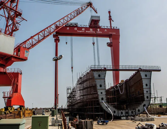
Automated welding in general fabrication spans structural components, wear-facing parts, and material handling equipment, where consistent quality reduces rework and extends service life. Fixture and positioner selection are the primary drivers of weld repeatability, as even minor positional deviations create defects that cause premature failure. For parts used in bulk and minerals handling, this impact is amplified: 67% of wear in both industries stems from abrasion, so inconsistent hardfacing creates uneven wear patterns that shorten operational lifespans.
Process Fundamentals
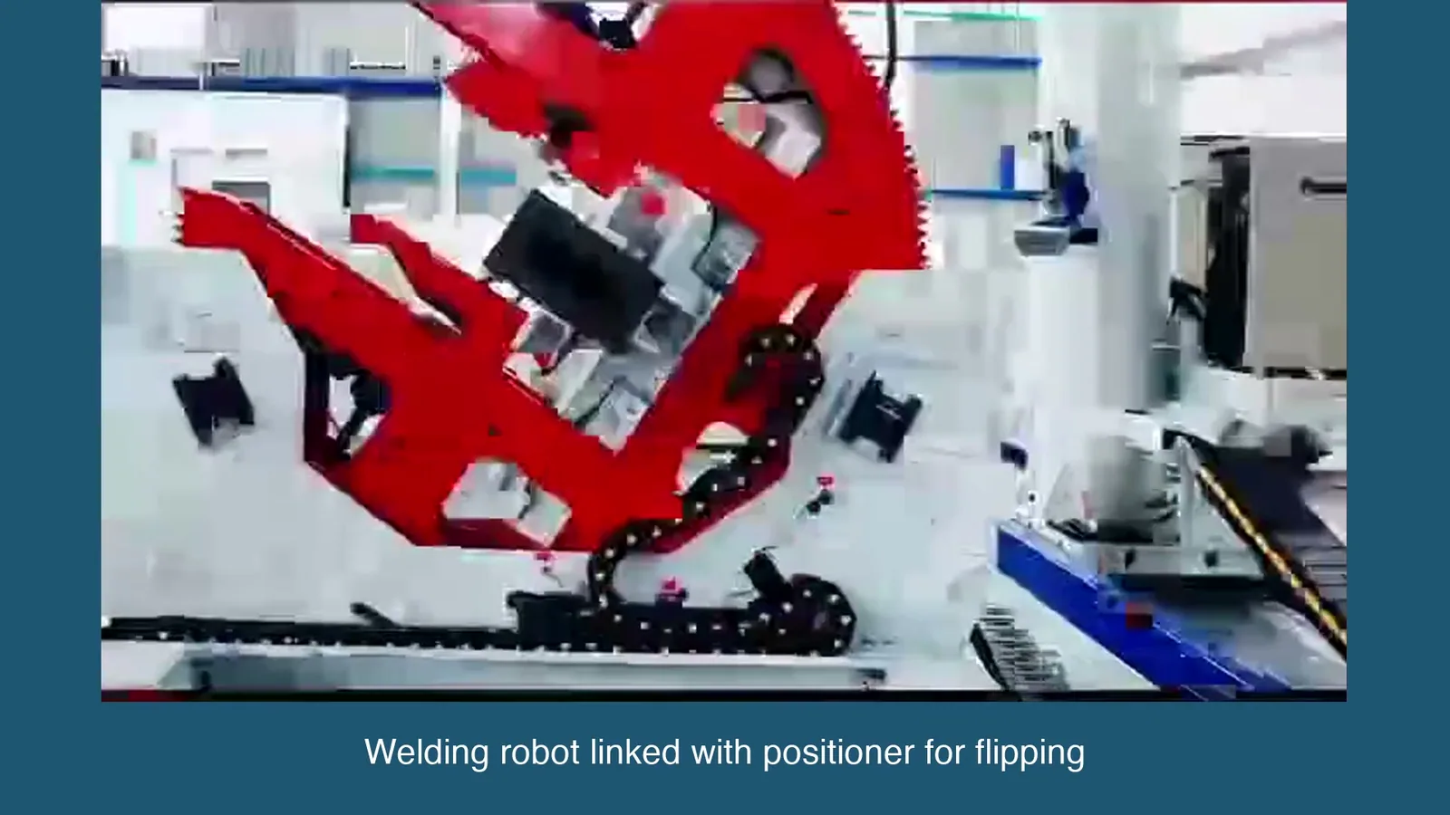
Automated welding repeatability relies on two core equipment functions: fixtures secure workpieces to maintain joint alignment and minimize thermal distortion, while positioners adjust orientation to keep the weld joint in an optimal flat/horizontal position for consistent torch access. For hardfacing, typical parameters include 1.0 to 2.5 kJ/mm heat input, 3 to 8 kg/h deposition rate, and 30 to 50% bead overlap, all dependent on stable fixturing and consistent positioner motion.
For vertical mill roller hardfacing, positioners must support multi-ton loads while maintaining rotational accuracy, as wear conditions vary by mill type: raw mills operate with material beds exceeding 300mm thick, imposing uniform high abrasion, while slag or clinker mills have beds only 50 to 80mm thick, creating localized high-stress wear. Both require consistent bead overlap to prevent wear breakthrough. For loader buckets handling hot slag (>500 deg C) from blast furnaces, abrasion is significantly amplified by elevated temperatures, making even small weld inconsistencies critical failure points.
| Component Type | Fixture Type | Positional Tolerance (mm) | Clamping Force (kN) | Heat Dissipation |
|---|---|---|---|---|
| Structural beams | Modular jig | +/-0.3 | 15-25 | Low (air-cooled) |
| Bulk handling wear buckets | Hardened custom fixture | +/-0.2 | 30-45 | Medium (water-cooled base) |
| Vertical mill rollers | 3-jaw self-centering chuck | +/-0.15 | 50-70 | High (integral water cooling) |
| Hot slag handling components | Ceramic-backed fixture | +/-0.2 | 25-40 | High (water-cooled + heat shields) |
| Application | Load Capacity (kg) | Rotational Speed (rpm) | Tilt Range (degrees) | Angular Accuracy (degrees) |
|---|---|---|---|---|
| Structural beam fillet welding | 1000-3000 | 0.5-2 | 0-90 | +/-0.5 |
| Loader bucket hardfacing | 500-2000 | 1-3 | 0-120 | +/-0.3 |
| Vertical mill roller cladding | 3000-10000 | 0.2-1 | 0-180 | +/-0.1 |
| Hot slag chute hardfacing | 800-2500 | 0.8-2.5 | 0-135 | +/-0.2 |
Common Defects: Root Causes and Countermeasures
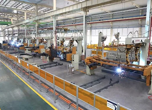
Most automated welding defects in general fabrication trace to fixture or positioner performance issues. Below are root causes and corrective actions tied directly to equipment selection and maintenance:
- Sidewall lack of fusion: Root cause: Fixture misalignment shifts the joint by >0.3mm, moving the torch off-center; positioner tilt error >1 deg creates an improper work angle. Countermeasure: Perform weekly fixture alignment checks with dial indicators; calibrate tilt encoders monthly to maintain +/-0.2 deg accuracy.
- Uneven hardfacing bead height: Root cause: Positioner rotational speed varies by >10% across the workpiece circumference; insufficient clamping force allows workpiece shift during multi-pass welding. Countermeasure: Specify positioners with closed-loop speed control; verify clamping force per batch with a calibrated torque wrench, matching values to Table 1 requirements.
- Distortion-induced joint misalignment: Root cause: Fixtures lack adequate heat dissipation, causing uneven thermal expansion; fixed-position fixturing leads to gravity-driven distortion during high-heat hardfacing. Countermeasure: Select water-cooled fixtures for applications with heat input >1.2 kJ/mm; use continuously rotating positioners to distribute heat evenly across the weld zone.
Applicable Standards
Fixture and positioner selection must align with industry standards for weld quality and equipment performance:
- ISO 15609: Specification and qualification of welding procedures for metallic materials — defines fixture alignment requirements for welding procedure qualification records (WPQRs).
- AWS D1.1/D1.1M: Structural Welding Code — Steel — specifies maximum joint misalignment tolerances for automated welding, directly tied to fixture positional accuracy.
- ISO 14324: Resistance spot welding — evaluation of positioners and fixtures — provides standardized test methods for verifying fixture repeatability across production batches.
- AWS D14.3: Specification for Hardfacing for Wear Resistance — requires consistent weld deposition thickness, which depends on stable positioner speed and fixture alignment.
Pre-Weld Fixture & Positioner Inspection Checklist
Perform this checklist before each production batch to ensure repeatable quality:
- Fixture checks: Verify all clamping points engage fully; measure clamping force with a calibrated torque wrench to match Table 1 values. Confirm positional tolerance via dial indicator or CMM, ensuring alignment within application-specific limits. Inspect water-cooling channels for blockages; confirm coolant flow rate >=10 L/min for high-heat hardfacing applications.
- Positioner checks: Calibrate rotational speed with a tachometer; confirm speed variation <5% across full workpiece rotation. Test tilt angle accuracy with a digital inclinometer; verify maximum tilt error is less than 0.3 deg for hardfacing tasks. Confirm load rating has a 25% safety margin relative to workpiece weight for dynamic rotation/tilt loads.
- Workpiece setup checks: Confirm full seating of the workpiece in fixture locators; no gaps >0.1mm between workpiece and locator surfaces. Verify joint alignment matches WPS requirements; add precision shims if misalignment exceeds 0.2mm.
Frequently Asked Questions
Q1: How often should fixtures and positioners be recalibrated for high-volume general fabrication?
A1: For 2-shift production with >50 workpieces per week, recalibrate fixtures monthly and positioner encoders every 3 months. For low-volume high-precision hardfacing (e.g., vertical mill rollers), recalibrate fixtures biweekly and positioners monthly to maintain tight tolerances.
Q2: Can modular fixtures match the repeatability of custom fixtures for hardfacing applications?
A2: Modular fixtures achieve +/-0.2mm positional tolerance, sufficient for most bulk handling wear components. For applications requiring <0.15mm tolerance (e.g., vertical mill roller cladding), custom fixtures with hardened locators are required to withstand repeated clamping and thermal cycling.
Q3: How does positioner speed consistency impact wear component service life?
A3: Rotational speed directly controls deposition rate and bead overlap. Consistent speed (variation <5%) ensures uniform 30-50% overlap, critical for components exposed to the 67% abrasion-driven wear common in bulk and minerals industries. Inconsistent speed creates thin hardfacing spots that fail 2-3 times faster, especially when handling hot slag (>500 deg C) where abrasion is amplified by elevated temperatures.
Key Takeaways
- Fixture positional tolerances of +/-0.15 to +/-0.3mm are required for general fabrication automated welding, with tighter limits for hardfacing components.
- Positioners with closed-loop speed control and +/-0.2 deg angular accuracy ensure uniform deposition, extending service life of abrasion-exposed parts.
- Pre-weld inspection of fixture clamping force, alignment, and positioner calibration reduces defect rates by up to 40% in high-volume production.
- Compliance with ISO 15609 and AWS D1.1/D1.1M ensures fixture/positioner selection meets industry quality standards.
BIQEE @ DESAN ELECTRIC supplies welding automation systems for the General Fabrication sector. For technical selection support, contact https://biqee.cn.