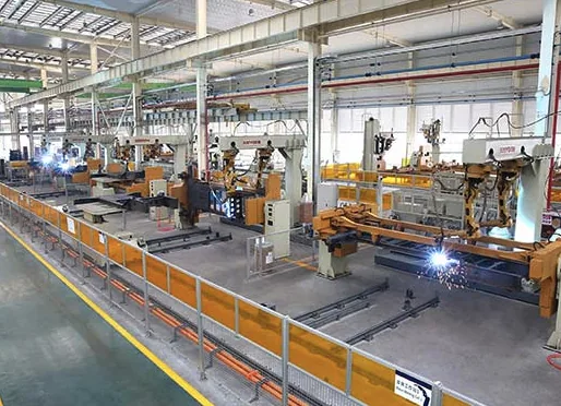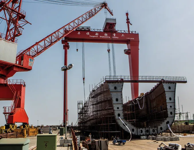
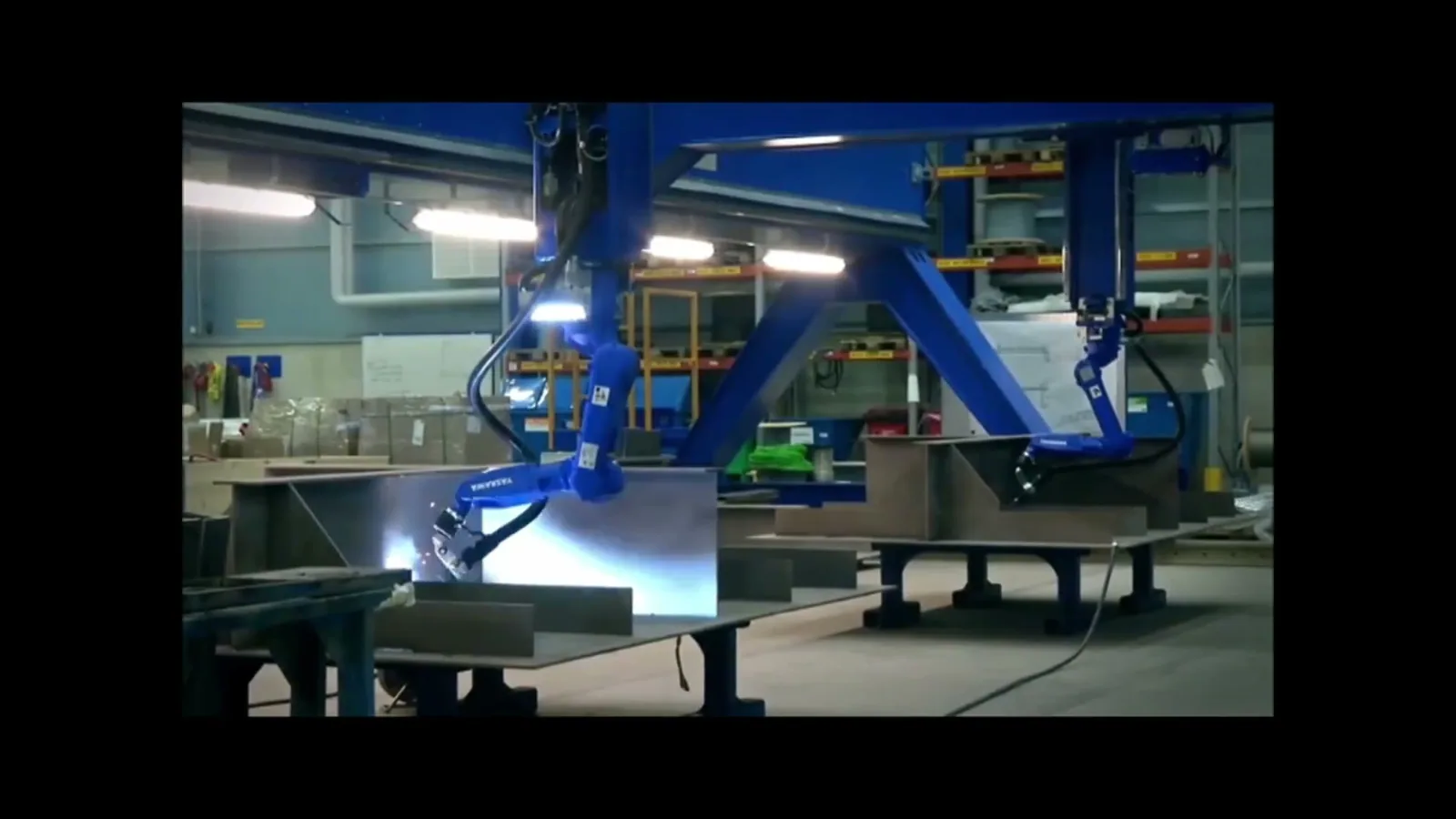
What Actually Changes on the Floor When the Arc Becomes Programmed
Automation does not remove welding difficulty; it relocates it. In a rail bogie or automotive chassis cell, the arc is usually the best-behaved element in the building. The problems that reach the production meeting are thermal, mechanical, and documentary: a part that was too hot for pass four, a fixture that wore 0.3 mm and moved the wire off the joint, a deposition log that reads 2.1 kg/h while the job was quoted at 4.5 kg/h.
A fabrication manager evaluating a cell has to plan around those three failure surfaces, not around the robot’s repeatability specification.
The Robot Repeats a Bad Thermal Boundary Condition
Preheat gets attention because it happens before the arc starts and can be signed off at shift start. Interpass temperature is what actually decides whether pass three behaves like pass one, and it is the parameter a cell will happily violate. The robot does not tire, does not stop for a break, and has no feel for a part still sitting at 340 C.
On a 20 mm HSLA bogie section, letting the joint cool to ambient between passes re-runs a fast-cooling experiment on every pass; letting the same section soak at 350 C heat-treats the heat-affected zone into a toughness problem. The number that matters is not a single interpass value but a window, and the physical range that controls the outcome is the 800500 C cooling interval.
Deposition Rate and Arc-On Time Are Two Different Businesses
The production log is the first place automation flatters itself. A cladding cell can sound steady, produce an acceptable bead profile, and still run at 2.1 kg/h against a quoted 4.5 kg/h. Deposition rate tracks wire feed speed, travel speed, and heat input.
Arc-on time excludes setup, handling, inspection, and rework, and it is where most of the lost shift actually sits. A cell welding at 6.4 kg/h with arc-on time at 38% delivers less finished work than the same cell at 5.2 kg/h and 55% arc-on. Both numbers belong in the quotation and on the shift-start sheet, because both are controlled parameters under the quality systems that govern rail and automotive work.
Fit-Up and Changeover Move onto the Critical Path
Manual welding absorbs fit-up variation through the welder’s eyes and hands. An automated cell does not absorb it; it either faults out or welds the wrong place. A two-hour tube changeover can hide behind excellent weld parameters, and a fixture worn by 0.3 mm can move the arc off a 23 mm root gap without tripping any alarm. When a manager budgets a cell, the fixture, the seam tracking, and the changeover procedure deserve the same scrutiny as the power source and the program.
The Thermal Window Is the Parameter You Actually Own
Preheat, interpass temperature, and post-weld heat treatment are usually presented as three separate clauses. On the floor they are one control problem: how fast the weld zone cools through the transformation range, and how much heat remains in the part when the next pass starts.
Preheat sets the starting point. Interpass temperature is the real-time variable. Post-weld heat treatment cleans up residual stress after the fact and is not a rescue plan for a thermal history that was wrong during welding.
Two Failure Modes, One Range
Running too cold is the familiar failure. Fast cooling through 800500 C produces hard martensite in the heat-affected zone and does not give diffusible hydrogen time to escape. On a thick section the result is a cold crack that appears hours or days after the part has left the cell.
Running too hot is the less obvious failure and the one automation makes more likely: coarse prior-austenite grains, loss of toughness, increased distortion, and higher dilution on the first layer of a cladding deposit. For HSLA rail and chassis steels, a cooling time of roughly 815 seconds through the 800500 C interval is a practical target band, and the procedure should state the range rather than leave it to the cell’s default dwell.
Typical Windows in Rail and Automotive Fabrication
- Preheat for 20 mm HSLA bogie frame and axle housing work: 120200 C, applied over a width of at least four plate thicknesses each side of the joint.
- Preheat for rail wheel overlay and heavy repair cladding: 150200 C, held until the first pass is completed.
- Interpass ceiling for HSLA bogie and chassis work: 250 C. Above that, toughness and dilution drift become the dominant risks.
- Interpass floor where hydrogen is a concern: 150 C. A part allowed to fall below this between passes must be re-heated and re-recorded, not simply re-struck.
- Post-weld heat treatment for stress relief on thick rail fabrications: 560620 C, with a soak of about one hour per 25 mm of section thickness and controlled heating and cooling rates.
Holding the Window in an Automated Cell
The measurement has to be built into the cycle, not left to an operator with a handheld thermometer. Contact thermocouples at a fixed distance from the weld toe, or a trailing sensor reading the interpass surface, should feed cell logic that can hold, dwell, or alarm.
A practical arrangement is a minimum dwell after each pass, a measured interpass reading before the next arc start, and an automatic hold if the reading exceeds 250 C. The cell program should also cap the number of consecutive passes in one region so that heat does not accumulate in a corner of a bogie side frame.
Records need to show the reading, the pass number, and the time, because a thermal log reconstructed after the shift is not a record.
Bevel, Root Gap, and the Parameter Window on Thick Plate
Thick-plate automated welding in this sector covers roughly 1 mm to 100 mm wall thickness, but the parameters only work if the joint preparation is inside tolerance. The most common cause of a failed automated root is not the arc; it is a bevel that closed up, a land that was too thick, or a fit-up gap that varied along the seam.
Joint Preparation Decides Whether the Parameters Can Work
For a 22 mm rail bogie side frame in a double-sided V configuration, a 30 bevel per side with a 23 mm root gap and a controlled land is a workable starting point. Squareness and bevel land must be checked before arc centering, because a seam tracker will follow a bad preparation faithfully.
If the root gap closes below 2 mm over part of the length, the cell will either fail to penetrate or increase current until it burns through; both outcomes are nonconformances waiting to be written. Fit-up should be held to within 1 mm of nominal gap over the full seam, and the fixture should be checked for wear at the start of every shift.
Current, Voltage, Travel, and Heat Input
A representative automated GMAW window for 2025 mm HSLA steel is 260320 A, 2630 V, and 0.350.6 m/min travel, giving a heat input of roughly 1.01.8 kJ/mm. For hot-wire arc cladding, the working window is about 1.53.5 mm layer thickness at 500600 A and 2630 V, with travel set to keep first-layer dilution below 15%.
Dilution above 15% on the first layer is a signal that the arc lingered or the travel speed was edited without updating the procedure. On multi-pass work, the interpass ceiling of 250 C and the heat input ceiling in the procedure qualification record both have to be respected; a travel speed change that raises heat input by 20% can take the procedure outside its qualified range even though the bead still looks acceptable.
Cladding and Orbital Work Are Separate Procedures
Cladding for corrosion and wear resistance runs on its own paper trail: layer thickness, dilution, overlap, and surface finish are specified separately from structural joint welding. Orbital tube work is different again. ASME B31.3 governs the procedure, and a 3.2 m Ra internal finish requirement is not unusual on hygienic or fluid-handling tube in automotive and rail auxiliary systems.
An orbital cell can miss penetration while its arc-on time sits at 38%, because the real loss is in tube changeover and fit-up. A two-hour changeover is not a welding problem, but it will be quoted as one if the estimator uses arc time alone.
Where It Fails: Defects, Causes, and Countermeasures
The defects that actually hurt in rail and automotive automated welding are few, and they are mostly predictable. Lack of fusion in a bogie load path and dilution drift on a cladding layer are procurement and setup problems before they are welding problems. The table below is the working version a fabrication manager can put in front of a supplier.
| Defect | Usual mechanism in a cell | Countermeasure | What to write into the specification |
|---|---|---|---|
| Lack of fusion, sidewall or root | Travel speed edited upward, heat input below procedure, bevel too narrow, wire aim drifted by fixture wear | Restore qualified parameters, verify seam tracking, check fixture and torch angle | Heat input 1.01.8 kJ/mm, 30 bevel per side, 23 mm root gap, fixture wear limit 0.3 mm, tracking verification each shift |
| Interlayer porosity | Gas flow or quality, contaminated wire, moisture, interpass debris not removed | Gas flow 1520 L/min, wire dry storage, interpass cleaning step in the cycle | Gas type and flow range, wire storage condition, interpass cleaning before each pass |
| Dilution drift on cladding | Arc lingered, travel speed changed, layer thickness above window | Cap first-layer dilution, log wire feed and travel per pass, run a 100 mm coupon per lot | First-layer dilution below 15%, layer thickness 1.53.5 mm, coupon before procedure change |
| Incomplete penetration on orbital tube | Poor squareness, excessive land, arc not centered, inadequate purge | Correct preparation before arc centering, verify land and squareness, check purge | Squareness within 0.1 mm, land 1.01.5 mm, internal finish 3.2 m Ra where specified |
| Hydrogen cold cracking | Interpass fell below minimum, fast cooling, no hold before post-weld heat treatment | Preheat maintained, interpass floor enforced, controlled cooling to the heat treatment temperature | Preheat 150200 C, interpass minimum 150 C, cooling time 815 seconds through 800500 C |
| HAZ grain coarsening and toughness loss | Interpass above ceiling, excessive heat input, passes stacked without dwell | Cell logic to hold at 250 C, cap passes per region, qualified heat input ceiling | Interpass maximum 250 C, heat input upper limit, pass sequence and dwell shown on the traveler |
| Distortion on thin automotive sections | Heat input too high for thickness, unbalanced sequence, rigid fixture released too early | Lower heat input, balanced backstep sequence, controlled release temperature | Sequence drawing, heat input range by thickness, release temperature and fixture inspection interval |
Specifying and Buying: The RFQ, the Procedure, and the Records
Most automation disappointments are written into the request for quotation. A buyer who opens with a process name invites a price for that process; a buyer who opens with the duty and the joint family invites a solution. Three items belong in the RFQ before anyone discusses equipment: the joint family and throat thickness, the base material and section range, and the duty cycle including inspection and rework.
Then the supplier can justify the process against the duty rather than the other way round.
The RFQ Needs Numbers, Not Adjectives
- Joint detail: bevel angle, root gap, land, and the tolerance on fit-up at the cell.
- Thermal requirements: preheat range, interpass window, cooling-time target, post-weld heat treatment condition.
- Acceptance criteria: fusion and penetration requirements, porosity limits, dilution limit for cladding, surface finish where relevant.
- Production numbers: required deposition rate in kg/h, arc-on time as a percentage of cycle, and measured changeover time.
- Records: interpass readings per pass, wire feed and travel logs, fixture wear checks, coupon results.
- Spares and training: torch, liner, drive roll, and sensor spares held on site; operator and maintenance training hours.
The Paper Trail That Carries the Numbers
For rail work, EN 15085-2 pegs the manufacturer certificate class to an ISO 3834 quality level, and ISO 3834 requires production to follow a qualified welding procedure specification. The traveler for a 22 mm bogie side frame should name the procedure, the welding operator, and the inspection hold points before the first arc.
ISO 14732 is the clause many shops forget: it covers the qualification of welding operators for mechanized and automatic equipment, which is a separate qualification from the welder’s. For automotive work, IATF 16949 turns deposition rate and arc-on time into controlled parameters with a document trail, not shop-floor trivia.
A supervisor who can quote 6.4 kg/h and 52% without opening a folder has a quality system doing its job.
Acceptance Criteria You Dictate
Do not inherit an acceptance criterion from a previous job because the drawing looked similar. State the fusion requirement, the dilution ceiling, the porosity limit, and the surface finish in the RFQ, and require the supplier to quote against them. A supplier who cannot produce a qualified procedure for the stated heat input and interpass window should be treated as an unqualified supplier, not as a cheaper option.
When two offers look identical on the cover page, compare the deposition rate, the arc-on time, the changeover time, and the coupon frequency; those four numbers explain most of the price difference.
Cost per Metre and Where Automation Is Not Worth It
Cost per metre is the number that survives the quotation meeting. Build it from wire and gas consumption, labour for the cell operator and fitter, fixture amortization, changeover time, inspection, and rework. As a working range for rail and automotive structural work, a well-run automated cell can land at roughly 1824 per metre on a repeating family of joints, against 3545 per metre for manual welding of the same joint, but only when arc-on time is above about 50% and changeover is under 30 minutes.
When arc-on time falls to 38% and changeover runs two hours, the automated cost per metre can exceed the manual figure while the deposition log still looks healthy.
Reading Two Quotes Without Getting Played
Ask both suppliers for the same four figures: deposition rate in kg/h, arc-on time as a percentage of cycle, changeover time in minutes, and first-layer dilution for cladding work. A quote built on 4.5 kg/h and 52% arc-on is a different proposition from one built on 2.1 kg/h and 38%, even if the equipment price is identical.
Then add the cost of the fixture, the thermal monitoring, and the records system, because those are the items that decide whether the cell hits its quoted rate. A budget that covers the robot but not the fixture and the interpass control is a budget for a demonstration, not for production.
Jobs to Keep Manual
Automation is not worth it when the work is low volume and high mix. A shop running fewer than about 20 metres of a given joint per setup, or changing family more than twice a shift, will spend more time on fixtures and programming than on arc time. It is also not worth it where fit-up variation routinely exceeds 2 mm, where access is restricted enough that a torch cannot be presented at the correct angle, or where the section is below about 3 mm and distortion control dominates.
One-off repair and rework should stay manual; a cell set up for a single repair is a cell that has stopped producing. Finally, do not automate where the only budget is for the power source and robot. Without thermal control, fixture maintenance, and a records system, the cell will produce nonconformances faster and more consistently than a manual welder ever did.
The Decision That Actually Matters
The question is not whether a robot can run the arc. It can. The question is whether the shop can hold the thermal window, the fit-up, the fixture, and the paperwork that the arc depends on. Run a 100 mm coupon on the real base and filler combination before anyone touches the procedure.
Measure interpass temperature on the third pass, not the first. Log deposition rate and arc-on time for a full shift, including changeover. If those numbers hold, the cell will pay for itself. If they do not, the automation has simply moved the variability somewhere the production manager cannot see it until the parts fail inspection.
Automated welding in other sectors
If you work across more than one sector, these guides use the same engineering logic with the numbers that differ by industry.
Welding Robot System
Technical Specifications:
| Model | Payload (kg) | Reach (mm) | Axis | Position Repeatability (mm) | Protection Class |
|---|---|---|---|---|---|
| RB-6 | 6 | 1450 | 6 | 0.03 | IP54 |
| RB-10 | 10 | 1800 | 6 | 0.05 | IP54 |
| RB-20 | 20 | 2000 | 6 | 0.05 | IP67 |
| RB-50 | 50 | 2200 | 6 | 0.07 | IP67 |
| RB-100 | 100 | 2600 | 6 | 0.08 | IP67 |
| RB-166 | 166 | 3000 | 6 | 0.10 | IP67 |
Note: Integrated welding package (power source, wire feeder, torch). Seam tracking and touch sensing available. Offline programming support.
For detailed specifications and pricing, contact us at [email protected] or visit https://biqee.cn.
Conclusion
Choosing the right welding automation solution is key to improving productivity and quality in your fabrication operations.