The Block Does Not Care That the Cell Is New
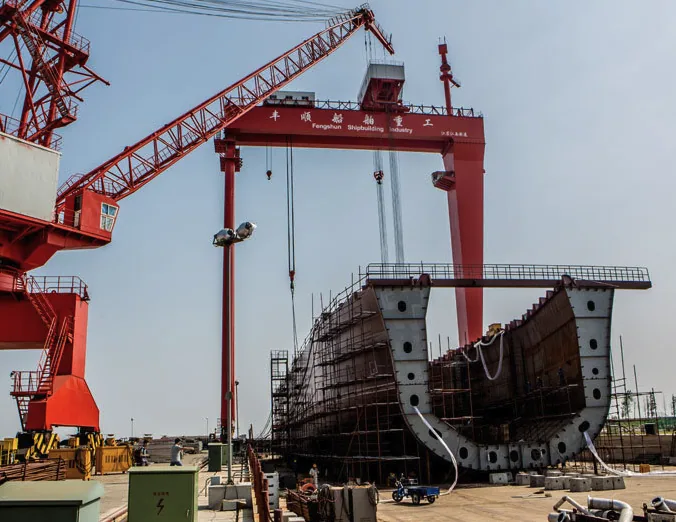
A hull block does not care that your automated cell is new. It cares that the welding procedure specification, the procedure qualification record and the fit-up sheet agree with one another on the morning the panel is tacked. Automated welding in shipbuilding is routinely sold as one thing and is actually four: hull panels, stiffener assemblies, corrosion-resistant cladding and pipe spools.
Each has its own failure mode, its own paper trail and its own economics. The useful question for a fabrication manager is not “what defects occur” but “which clause put that parameter on my shop floor, and what record proves it stayed there for the whole shift.”
The Qualification Record Is the Operating Envelope
Start with the procedure qualification under ISO 15614-1 for arc welding of steels and nickel alloys. That record is not a filing cabinet ornament; it defines the band you are permitted to run. For AH36 and DH36 hull joints, heat input is commonly held at 1.22.5 kJ/mm, but the qualified range is narrower than that headline figure.
If the procedure was tested at 2.0 kJ/mm, the test supports a band around 2.0, not the whole 1.22.5 spread. A cell programmed to a fixed 1.4 kJ/mm on a 12 mm butt is outside its qualification unless the record covers it, and the toughness of the heat-affected zone is the first thing that changes.
The arithmetic is simple enough to check on a phone. Heat input in kJ/mm equals voltage times amperage times 60, divided by travel speed in mm/min times 1000. At 30 V, 700 A and 800 mm/min that is 1.58 kJ/mm; drop the travel speed to 550 mm/min and the same settings deliver 2.3 kJ/mm.
Nothing about the power source changed, only the travel command. This is why travel speed, not current, is the parameter that most often drifts out of window once a cell is in production, and why the calibration log for the travel axis matters as much as the one for the ammeter.
Fit-Up Is the First Inspection Point, and It Happens Before the Arc
AWS D1.1 and SOLAS II-1 traceability requirements converge on the same practical point: the joint geometry is part of the procedure, so it is part of the evidence. For a typical 60 degree included bevel, specify and measure the angle to plus or minus 2.5 degrees, the land at 1.52.0 mm and the root gap at 02 mm.
Commercial seam-tracking systems will follow a variation of roughly one millimetre without complaint. They will not repair a four millimetre gap. If your plate shop routinely delivers fit-up variance above 2 mm, the cell will spend the shift either in fault or filling gaps with uncontrolled parameters that no procedure covers.
Fit-up correction is cheaper than the cell, and it is always cheaper than the requalification.
Cladding Dilution Belongs in the Calibration Log
Corrosion-resistant cladding on ballast tanks and cargo areas is a dilution problem disguised as a welding problem. Under ISO 14323 the interesting figure is the depth of base-metal penetration into the deposit. Keep dilution at or below about 10% for typical austenitic or duplex overlays, and record it from a macrosection at the start of every shift and after any wire batch, flux or gas change.
A two-point drift in dilution is invisible in the finished surface and shows up as a corrosion allowance failure six to eight years later, at which point the conversation is about a docking, not a weld. That macrosection is a control instrument, not a quality formality.
Thermal Control: Buy the Loop or Buy the Discipline
Thick HSLA hull plate, ballast-tank cladding and pipe spools punish sloppy thermal control. The weld looks acceptable at 24 hours and cracks at 72 hours, because hydrogen has nowhere to go and the heat-affected zone is already at its toughness limit. The real decision is not “automated or manual.” It is whether closed-loop thermal control is bought as part of the welding cell, or whether you keep field control enforced with calibrated instruments and a supervisor who owns the hold points.
Both routes work. They fail in completely different places.
Route A: Closed-Loop Thermal Control
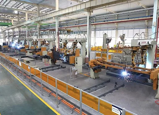
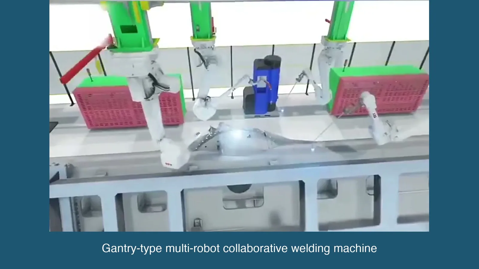
Submerged-arc panel lines, GMAW stiffener gantries or hot-wire cladding heads fitted with induction or resistance preheat, infrared sensors on the joint, PLC-enforced pass waits and automatic logging of interpass data. The advantage is that the recipe, not the operator, decides when the next pass starts.
The disadvantage is capital, commissioning time and recipe discipline: every new joint geometry needs its own thermal recipe proven on the worst-case thickness, and a sensor that is not calibrated will block a pass for the wrong reason until someone overrides it and someone always overrides it.
Route B: Manual Field Control
Handheld preheat, contact thermometers or temperature-indicating crayons, manual records and a supervisor who signs the hold point before the next pass is permitted. Capital cost is a fraction of Route A. Its weakness is variance: two shifts will apply two different standards of diligence, and the record tells you what was written down, not what was measured. Route B is defensible when joints are short, geometries change hourly and the cell utilisation needed for Route A simply does not exist.
What the Window Looks Like on the Floor
For 40 mm AH36 at a carbon equivalent of 0.350.40%, expect a preheat band of roughly 100150 C, set by thickness and hydrogen class rather than by habit. The interpass ceiling for many hull structural grades is 250 C, tightened to around 200 C where toughness testing is demanding.
Where post-weld heat treatment is specified, it typically sits at 580620 C with heating and cooling rates capped near 55 C per hour above 300 C. The engineering point is that a 250 C ceiling on a 60 mm multipass joint is easy to breach: at 700 A and low travel speed the plate soaks, and the next pass starts hotter than the last one finished.
That is a toughness deviation, not a cosmetic one, and it will not appear until the Charpy results come back.
Where the Loop Earns Its Keep
Closed-loop thermal control pays where joints carry more than about eight to ten passes per metre of weld, where the base metal sits above 40 mm, where the specified interpass ceiling is tight, or where the class society requires time-stamped thermal records. It does not pay on 8 mm stiffeners welded in two passes over 200 m runs: the sensor package and its calibration burden cost more than the defects it prevents.
The honest threshold is between those extremes, and it is set by your rework rate, not by the vendor’s brochure.
Two Levers on One Throughput Number
Deposition rate and arc-on time multiply into the same output figure. A 10% gain on either buys the same extra metres of weld per shift, which is why the two get quoted at each other in meetings. The symmetry stops there. Rate is bought with power source capacity, wire, shielding gas and sometimes a second torch.
Arc-on time is bought with fixtures, floor layout, seam tracking and discipline. Shops that spend heavily on the first and ignore the second spend most of the shift watching an idle arc.
Agree the Definitions Before Benchmarking Anything
Deposition rate is kilograms of sound weld metal per arc hour. Spatter, crater fill and cut-out rejects come out of the numerator, which is why two cells with identical nameplate capacity report different numbers. Arc-on time is the share of scheduled shift with an active arc, with start and stop tapers excluded from the clock.
Hull panel cells typically sit at 3045%; well-fixtured panel lines with automatic fit-up and no manual tacking reach 5055%. Anything quoted above that without a fixture description is a sales figure.
Where the Dead Hours Hide
They hide in fit-up and tacking, torch cleaning and tip changes, consumable replenishment, gas purge, program prove-out, and waiting for interpass cooling. Take a cell at 35% arc-on across two ten-hour shifts: that is seven arc hours per day. At 5 kg/h of sound deposit that is 35 kg.
Moving arc-on to 45% on the same schedule yields nine arc hours and 45 kg a 10 kg daily gain bought with fixtures and layout, at essentially zero consumable cost. The same 10 kg bought through deposition rate requires a larger power source, more wire per hour and usually a second torch.
That is the comparison to put in the capital request.
The Clock Route and the Rate Route Cost Differently
The clock route means hydraulic clamps, self-aligning roller beds, seam tracking, a floor layout that stages plates instead of hunting for them, and the discipline to keep the cell fed. Tooling for one panel cell commonly lands in the low-to-mid six figures, but the recurring cost is low and the gains persist.
The rate route means bigger power sources, tandem or twin wire, more sophisticated gas and flux handling, and a heavier maintenance burden. It also bites back: on cladding, pushing deposition from 8 to 15 kg/h without controlling the arc will raise dilution past 10% and quietly downgrade the corrosion resistance you were paid to provide.
On thick plate, higher current with the same travel speed raises heat input and can push you out of the qualified window. Rate must be capped by dilution and by the procedure, not by what the power source can deliver.
Write the Parameter Envelope Into the RFQ
An enquiry that says “AH36, submerged arc, automated” is not a specification; it is an invitation to quote a brochure. Thick plate in shipbuilding runs from 10 mm to 100 mm, welds can account for up to 30% of structural weight, and rework on those joints frequently consumes 1520% of the welding spend.
The buyer’s task is to purchase a controlled parameter envelope, evidence that the envelope was qualified on the worst-case joint, and a commercial offer that prices rework risk honestly.
Give every bidder the production thickness range, joint types, bevel angle with tolerance, land width, root gap range, and the base-metal carbon equivalent range 0.350.40% for AH36 is a different welding problem from 0.42%. State preheat and heat input as tied ranges, not single values, with the qualification standard named.
State the dilution limit for any cladding scope. State the deposition rate you expect at the qualified parameters and the arc-on time you expect the cell to achieve in your bay, with the fixture scope that makes it possible. Then ask what the bid assumes about fit-up.
What the Low Bid Leaves Out
Typically: fit-up correction and its labour, spares and consumable cost over five years, sensor calibration, operator and maintenance training, commissioning on the worst-case joint rather than a demonstration plate, and the requalification cost for each thickness or joint variant your production actually contains. A bid that assumes 3% rework on a thick-plate scope where the realistic figure is 15% has not found an efficiency; it has moved the cost into your budget in year two.
Compare offers on a cost-per-metre basis that includes those items, not on cell price.
| Route | Sound deposition | Heat input / thermal demand | Fit-up it survives | Where it fails |
|---|---|---|---|---|
| Submerged arc, single wire | 48 kg/h at 600900 A | 1.53.0 kJ/mm; interpass control essential | Root gap up to 2 mm, land 1.52.0 mm | Short welds under 400 mm, out-of-position work, poor flux handling |
| Submerged arc, tandem or twin wire | 1525 kg/h | 2.03.5 kJ/mm; higher preheat demand | Tighter than single wire; distortion-sensitive | Narrow gaps, thick-to-thin transitions, anything needing frequent stop-start |
| Pulsed GMAW on a stiffener gantry | 35 kg/h at 250320 A | 0.61.2 kJ/mm; low distortion on thin sections | About plus or minus 1 mm | Heavy mill scale, plate draft, runs shorter than the torch approach time |
| Flux-cored arc, robotic or semi-automatic | 36 kg/h | 0.81.8 kJ/mm | Tolerant to 23 mm gap | Hydrogen control if consumables are stored badly; slag removal time |
| Hot-wire or strip cladding | 815 kg/h | Dilution capped at about 10% | Needs flat, clean, dry surface | Curvature, surface contamination, dilution creep at high current |
| Orbital pipe welding, GTAW or GMAW | 0.52 kg/h | 0.51.5 kJ/mm; narrow window on thin wall | Bevel and alignment within 0.5 mm | Pipe ovality, misalignment, spool rotation limits; low rate for large bore |
Where the Automation Case Collapses
Automation is not worth it in more situations than the sales literature admits, and saying so up front is what separates a capital plan from a purchase order. The following conditions should stop the project or redirect it.
- Lot sizes below about ten similar joints. Programming, prove-out and fixture cost per metre exceed the manual route by a wide margin, and the learning never amortises because the next block is different.
- Welds shorter than roughly 400 mm. Approach, prove-out, retract and inspection consume more time than the arc does. Arc-on time collapses regardless of deposition rate.
- Routine fit-up variance above 2 mm. The cell will fault constantly or run unprotected parameters. Spend the money on plate preparation and jigs first; buy the cell afterwards, if at all.
- Confined access double bottoms, small tanks, cofferdams. No gantry fits, and the semi-automatic route with a trained
Automated welding in other sectors
If you work across more than one sector, these guides use the same engineering logic with the numbers that differ by industry.
Self-Aligning Welding Rotator (SAR Series)
Technical Specifications:
Model Max Load (tons) Vessel Dia (mm) Wheel DiaWidth (mm) Motor Power (kW) Wheel Speed Overall Dim (mm) SAR5 5 250-2300 250140 0.75 0.1-1 m/min 1620690700 SAR10 10 320-2800 300170 1.5 0.1-1 m/min 1880780820 SAR20 20 500-3500 350180 2.2 0.1-1 m/min 2250930950 SAR40 40 600-4200 400200 3.0 0.1-1 m/min 250010151050 SAR60 60 750-4800 450220 4.0 0.1-1 m/min 300012001100 SAR80 80 850-5000 500240 4.0 0.1-1 m/min 320012001250 SAR100 100 1000-5500 50080 (PU) 5.5 0.1-1 m/min 350014101350 SAR150 150 1000-6000 500220 (Metal) 6.0 0.1-1 m/min 42009001450 SAR200 200 1800-8000 550260 7.5 0.1-1 m/min 48009001500 SAR250 250 1800-8000 660260 11 0.1-1 m/min 501011131600 SAR500 500 1800-8000 800300 15 0.1-1 m/min 560013702100 Note: Variable rotation speed (VFD). Wheels padded with heavy-duty rubber (SAR100 & smaller). Remote control with digital speed display.
For detailed specifications and pricing, contact us at [email protected] or visit https://biqee.cn.
Conclusion
Choosing the right welding automation solution is key to improving productivity and quality in your fabrication operations.